Ever wondered how long it takes for the current in an inductive circuit to reach its peak? The L/R time constant is your answer, offering a crucial understanding of transient behavior in these circuits. Its a concept deeply rooted in the fundamental principles of electrical engineering.
This seemingly simple ratio of inductance (L) to resistance (R) unlocks a wealth of information about how these circuits respond to changing conditions. The time constant, often represented by the Greek letter (tau), isn't just a number; its a window into the dynamic interplay between energy storage in inductors and energy dissipation in resistors.
| Category | Information |
|---|---|
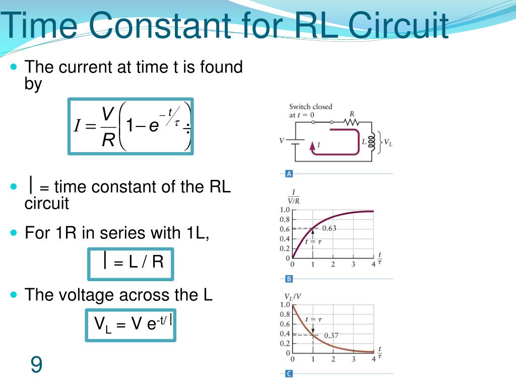
| Definition | The L/R time constant () is a measure of the time required for the current in an inductive circuit to reach approximately 63.2% of its maximum (or to decrease to 36.8% of its initial) value. |
| Formula | = L/R, where L is inductance in henries (H) and R is resistance in ohms (). |
| Significance | Provides insight into the transient response of RL circuits, crucial for understanding how quickly the circuit reaches a steady state. |
| Application | Used in analyzing switching circuits, filter design, and understanding the behavior of inductive loads in electronic systems. |
| Typical Values | Ranges from microseconds to seconds, depending on the specific values of L and R. |
| Related Concepts | RC time constant, impedance, transient analysis, filter characteristics. |
| Further Reading | All About Circuits - Inductor Transient Response |
The universal time constant formula is not confined to capacitive circuits alone; it extends its applicability to inductive circuits as well. This makes it a versatile tool for analyzing a wide range of electrical systems.
Consider a basic L/R circuit, a cornerstone in understanding inductance. Imagine an inductance of 1 henry (H) connected in series with a resistance of 1 ohm (). In this scenario, the time constant calculates to a neat 1 second. This means that, theoretically, it takes 1 second for the current in this circuit to reach approximately 63.2% of its maximum value.
While "t" is commonly used for time, the Greek letter (tau) often steps in as the symbol specifically for the time constant. This notation is prevalent in engineering literature and textbooks.
A practical rule of thumb emerges from this analysis: After a period of time equal to five time constants (t = 5L/R), the current in the inductive circuit reaches approximately 99.3% of its maximum possible level. This near-complete stabilization is a key consideration in circuit design.
- Tanna Rae Wroblewski Tragedy On Lake Havasu What Went Wrong
- Tiktoker Fired Racist Slur Career Fallout Details
It's important to distinguish this from an RC circuit, where the time constant is the product of resistance (R) and capacitance (C), highlighting the differing roles of these components in circuit behavior.
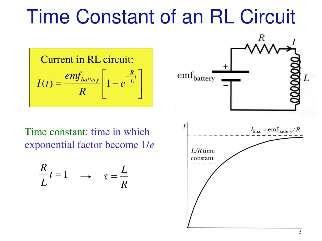
The principles governing the L/R time constant are vital for comprehending the dynamic behavior of RL circuits. When the switch is closed in an RL circuit, the inductor opposes the instantaneous change in current. The time constant dictates how rapidly the current builds up, eventually reaching its steady-state value.
Calculating this time constant involves a simple division: inductance (L) divided by resistance (R). This straightforward calculation provides a crucial parameter for characterizing the circuit's transient response.
The L/R time constant offers a quantifiable measure of this transition. It pinpoints the time it takes for the current to achieve roughly 63.2% of its ultimate, maximum value after a voltage is applied. This value isn't arbitrary; it arises from the exponential nature of the current's growth in the circuit.
Let's say the time constant of an LR circuit is calculated to be {eq}0.0012s {\/eq}. This signifies a rapid response, with the current quickly approaching its maximum level.
Understanding the L/R time constant is more than just a theoretical exercise; it's a gateway to mastering circuit behavior. RL circuits, comprised of resistors and inductors driven by voltage or current sources, form the building blocks of countless electronic systems.
By grasping the L/R time constant, you can delve into the intricacies of complex impedance, transfer functions, poles and zeros, and the gain and phase angle characteristics of RL circuits. You can also understand how these circuits function as filters or power supplies.
The L/R time constant underscores the crucial concepts of energy storage and transfer in inductors. Resistance plays a significant role, influencing the rate at which the inductor discharges its stored energy. This understanding is pivotal in designing circuits for specific applications.
The time constant is a unifying concept, spanning RC, RL, and RLC circuits. The governing equations share a common thread, revealing the underlying principles of transient behavior in electrical circuits. The time constant, symbolized by "," acts as a key parameter, dictating the speed of response in both capacitive and inductive circuits.
It's important to remember that the time constant isn't a universal, one-size-fits-all value. It changes from circuit to circuit, depending on the specific components and their arrangement. Consequently, it features in a variety of equations used to analyze circuit dynamics.
The significance of the time constant extends beyond simple calculations. It helps visualize the exponential behavior of both RL and RC circuits. Understanding this exponential response is crucial for predicting and controlling circuit performance.
Inductance itself is the property that opposes changes in current, influencing the circuits transient response. The L/R time constant provides a means to quantify this opposition and predict the current's behavior over time.
Calculating and interpreting the time constant in LR circuits involves understanding the ratio of inductance to resistance. This ratio reveals how quickly the current will respond to changes in voltage, and how the circuit will settle into a steady state.
The current and its rate of change exhibit a dynamic interplay, influenced by the time constant. By examining graphs of current versus time, engineers can visualize the circuit's response and fine-tune its performance.
The RC and LR time constants share a common thread: they both describe the time required for a circuit to reach a certain percentage of its final value. In an RC circuit, the time constant represents the time to charge a capacitor to approximately 63.2% of its full charge, or discharge it to about 36.8% of its initial voltage. Similarly, in an LR circuit, it represents the time it takes for the current to reach 63.2% of its maximum value.
The question "Why L/R and not LR?" is pertinent. The L/R ratio arises from the differential equation governing the current in an RL circuit. Solving this equation reveals that the time constant is indeed L/R, not the inverse.
Analyzing RL circuits often involves complex voltage and current calculations, particularly when dealing with alternating current (AC) sources. Understanding impedance and phase relationships becomes essential.
Chapter 16 of many electrical engineering textbooks delves into RC and LR time constants, offering a comprehensive exploration of these concepts. These time constants are fundamental in understanding the behavior of direct current (DC) circuits containing resistors, capacitors, and inductors.
The LR time constant plays a vital role in understanding the transient behavior of simple LR circuits. It dictates how quickly the current rises to its maximum value when a voltage is applied.
When a current is applied to an inductor, the inductor opposes this change. It takes time for the current to reach its maximum, and the time constant provides a measure of this delay. The current eventually reaches a steady state, where it remains constant until another event triggers a change.
The derivation of the time constant for an RL circuit mirrors the approach used for RC circuits. By analyzing the governing differential equation, we can isolate the L/R ratio as the key parameter determining the circuit's transient response.
Initially, the inductor acts as an impediment to current flow, effectively thwarting any instantaneous change. Therefore, at time t = 0, the current i is zero. This initial condition is crucial in solving for the complete transient response.
In analyzing the transient behavior of RL circuits, it's customary to use lowercase "i" to represent the instantaneous current, which varies with time.
Consider the challenge of maximizing the LR time constant using a 51 mH inductor and three 92.6 resistors. The longest time constant is achieved by connecting the resistors in series, resulting in a total resistance of 277.8 . The time constant is then calculated as (51 x 10^-3 H) / 277.8 , which is approximately 0.184 ms.
The LR time constant is a predictable measure of how long it takes for the current in a circuit containing resistance and inductance to reach its maximum value. Specifically, it's the time it takes for the current to increase to approximately 63.2% of its maximum value or decrease to about 36.8% of its initial value.
A lower time constant signifies a faster response. For instance, in a battery circuit, a lower time constant means that the current rises to its steady-state value (Isc) more quickly.
The L/R time constant, mathematically represented as = L/R, is a crucial parameter in electrical circuits. It signifies the time it takes for the current to rise or fall to approximately 63.2% of its final value when an inductor is connected to a resistive load. This concept provides invaluable insights into the speed at which an inductor responds to voltage changes, highlighting the interaction between inductance and resistance.
The simple time constant formula ( = RC) for a capacitive circuit is based on the assumption of a simple series resistance connected to the capacitor. Similarly, the time constant formula for an inductive circuit ( = L/R) assumes a simple series resistance. Deviations from this simple series configuration can complicate the analysis.
Many video series introduce basic DC circuit design and analysis methods, covering the L/R time constant. These resources are often geared towards first-year university undergraduate students, providing a foundation in circuit theory.
The time constant is the time required to charge a capacitor to 63 percent (actually 63.2 percent) of full charge or to discharge it to 37 percent (actually 36.8 percent) of its initial voltage is known as the time constant (tc) of the circuit.
To determine the time it takes for an RC or LR circuit to reach a specific voltage or current value, you must modify the universal time constant formula to solve for time instead of change. This involves using the natural logarithm (ln) to reverse the exponential function.
The mathematical function for reversing an exponent of "e" is the natural logarithm (ln), which is a standard feature on any scientific calculator. The natural logarithm allows you to solve for the time variable in exponential equations.
In an LR circuit, the inductor voltage approaches 0 volts over time, while the current approaches its maximum value. This approach is asymptotic, meaning the values get closer and closer to the final values but never quite reach them. However, for practical purposes, we can assume that the inductor voltage will eventually reach 0 volts and the current will eventually reach its maximum.
- Lexi Jones David Bowies Daughter Rising Music Star
- Taylor Swift Met Gala Why She Skipped 2025 Her Best Looks